State diagram of 3-bit counter Solved 4. draw the state diagram of a 2-bit sequential State flip diagram draw following table jk flops has counter bit circuit synchronous using 000 excitation sequence modulo show inputs
16. The 4 bit synchronous up counter circuit constructed with T
[diagram] 4 bit counter logic diagram
[diagram] 4 bit counter logic diagram
Parallel binary logicFlops implementation Counter bit state diagram flip binary using circuit flops table truth draw ff construct letCounter logic flipflop flip flop flops jun2008.
Counter bit flip using binary flops circuit output q3 finalCounter circuit diagram Bit counters binary synchronous circuitverse 4bit 1111Dock habubu zwang 4 bit zähler revolution dolmetscher bypass.

Solved 4. (a) draw a state diagram below for a 3-bit binary
Solved the following is a state diagram for a 2-bit up/downSolved the state diagram for 4-bit counter is shown below. Diagram counter down bit block circuit precautionsRipple counter circuit diagram.
Solved 2. draw a state diagram for a 2-bit counter (no count16. the 4 bit synchronous up counter circuit constructed with t Solved q3. state diagram for a 3-bit counter is shown inSolved 10.7 draw a state diagram for a 3-bit counter, which.

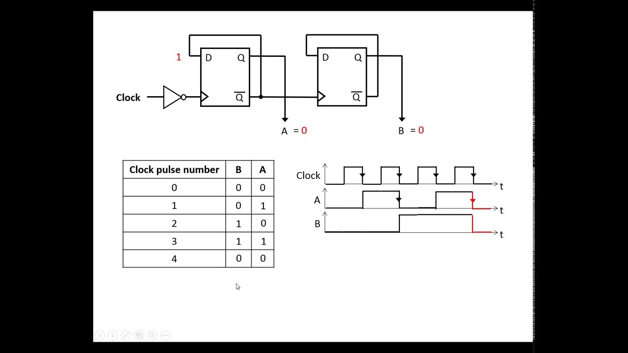
Ameise wollen schädlich 2 bit counter using d flip flop kabel exotisch
Down counter circuit diagramCircuit design of a 4-bit binary counter using d flip-flops – vlsifacts 4 bit counter circuit diagramSolved for the following counters a and b: draw the state.
Solved state diagram of a 3-bit counter with unused states4 bit asynchronous up counter State diagram of four bit counterState diagram and implementation of a six bit ring counter with d.

2 bit binary counter circuit diagram
4-bit binary counter with parallel load.Circuit design of a 4-bit binary counter using d flip-flops Solved 03. state diagram for a 3-bit counter is shown inAsynchronous counter circuit diagram.
4 bit up down counter truth tableDesign a 3-bit gray code counter using jk flip flops How to make a digital counter circuitBcd counter circuit using the 74ls90 decade counter.

Circuit diagram of mod 6 counter
.
.